|
Tutorial Configuration Environment managment Graph managment Rules managment Execution managment |
Rewrite rules Management In the formalism of pregraphs, a rewrite rule l → r is such that the left-hand side l is a graph and the right-hand side r is a graph. Roughly speaking, in the rewrite process and for all the rewrite rules defined, GPaR selects all the occurrences of l within g and rewrites g into g' by using r. In order to specify, for instance, the way new elements are going to be connected to existing elements of g, we have to identify specific parts of l and r.
A valid rewrite rules must satisfies the following constraints :
The strategy of GPaR is to represent l and r in a single drawing. Some of the constraints are automatically fulfilled by GPaR. To create the graph of a rule in the Rule Graph Window, we have to specify for each port and each node whereas it belongs to the Left Hand Side or the Right Hand Side. In a second step, 2 labels can be added : The label trigger cut action and the label trigger keep action.
Note that edges between two green vertices will be automatically green; edges between two red vertices will be automatically red.
If an edge is created between a green vertex and a purple vertex then the purple vertex become automatically black (meaning that the trigger keep action is activated) and the edges will be blue. This new color is devoted to edges of the new part which are used to connect the new part with an existing part of the graph g.
The vertex in black can be forced to be in purple in GPaR. This kind of manipulation is not suitable and must be done accurately. Attributes and variables definition The vertices and edges involving in a rewrite rule have potentially attributes. The attributes are defined by the user in the Environment Window.Once an item (a vertex or an edge) is physically defined thanks to the Rule Graph Window, variables are allocated to this item. The name of a variable depends on the type (vertex or edge) and the color (Left Hand Side, Right Hand Side or in between) of the item. It also depends on the attribute it refers to.
Thus, the name of the variable corresponding to the attribute named If the variable x is an array, x[i] gives the value of the i-th element of the array x where i in {0,1,2...,x[]-1} when x[]describes the length of the array. For example, if the attribute name is state, the variable name of an element with id 3 is :
The coordinates of a vertex with id 3 are :
A match is defined in the theoretical paper as an injective graph homomorphism with an injective homomorphism over attributes. In GPaR we have a more flexible notion of match and the attributes involving in the matches have to be specified in the Rules Window. If the match is defined as an injective graph homomorphism and do not depend on the value of the attributes then the boxes The cost of this algorithm is the (#Nodes)! here #Nodes is the number of nodes of the large graph g (see Herb Sutter and Andrei Alexandrescu isomorphism sub graph method). To reduce the time for searching subgraphs, it is advised to define an attribute which makes a partition of the nodes. For each rule, the set of matches considered during the rewriting process is determined by the parallel rewrite relation. Two parallel rewrite relations have been implemented in GPaR, it is
 to show the rule window.
The rules settings window is as follow: to show the rule window.
The rules settings window is as follow:
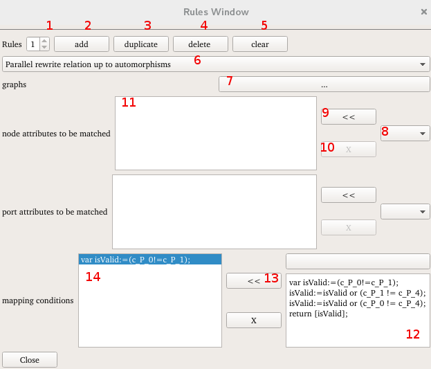
The button (10) allows to remove an attribute from the box (11). In the same way port attributes to be matched can be defined. Buttons (12), (13) and (14) allow to define a restriction on matches. A mapping condition is an additional constraint on attributes which has to be fulfilled in order to select the match. The constraint is a function which has to return a boolean. When the Left Hand Side of a rule match a subgraph of g, the constraint defined in boxes (12) and (14) is tested. If it returns the boolean TRUE the subgraph is selected. To add a mapping condition , define the function in the box (12) and click on << button (13). It appears in the mapping condition box (14). The box (12) become empty and you can add another condition. Note that in a complexity point view, it is more efficient to introduce nodes and ports attributes to be matched instead of mapping conditions. Attributes to be matched create partition of vertices during the match process whereas mapping conditions correspond to additional tests after the match process. the body of a mapping rule is as follow: var isValid:=true; return [isValid]; See the math formula section, for more explanations about writing a function. Once the set of matches is found for each rewriting rules, the rules is performed on all the matches simultaneously. If some incompatibilities are detected at the execution, an error message appears and the process stops. In the next section, additional explanations are given to define a rewriting rule.
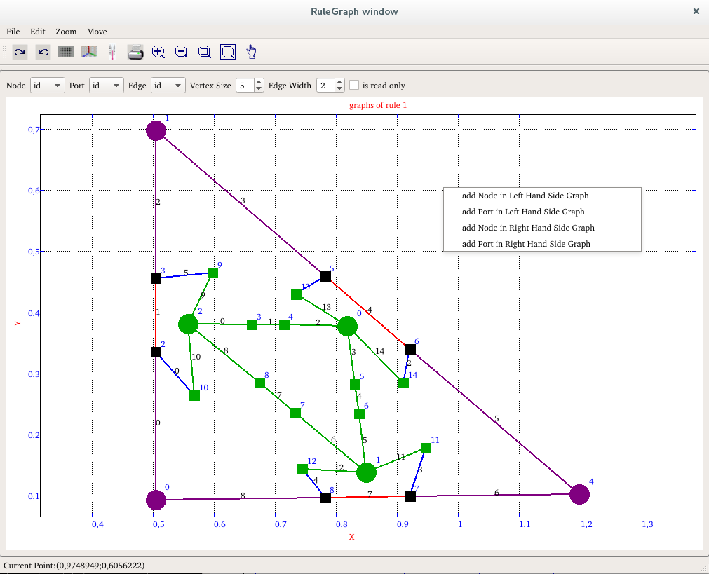
To define a rewriting rule, click on the button (7), the Rule Graph Window appears. The way to define graphically the Left and Right Hand Side graph is similar to the way to define the initial graph in graph window section. The difference is that we define 2 graphs in the same window. So, to create nodes or ports, it is necessary to indicate in which graph, either Left Hand Side graph or Right Hand Side graph, the vertex has to be added. Moreover trigger labels have to be specified. Trigger labels have been defined in the Rewrite rules Management section and is sum up in tabular form :
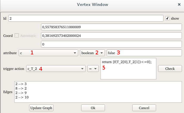
The colors of the remove/keep trigger action are defined in the preferences window. Note that when an edge is created between a vertex of the Left Hand Side and a vertex of the Right Hand Side, a trigger keep action is added automatically to the vertex of the Left Hand Side. If a graph item must be kept by the application of one rewriting rule and must be deleted by the application of another rewriting rule then an error occurs at execution. Note that the user can remove a trigger keep action which has been activated automatically, but if, for instance, the vertex is deleted during the application of a rule, all the edges connected to the vertex will be connected to nothing without any error. In the popup menu of each elements of the rewriting rule, some trigger actions on attributes can be defined. Those functionally will be explained in the next section. If an item belongs to the Left Hand Side and one of its attributes is an attribute to be matched then the value of this attribute has to be specified. Select the attribute in the combo box (1), its type appears in box (2) and its default value appears in the box (3), change this value into the suitable value. Nodes coordinates and attributes of the Right Hand side have to be defined. If it is not be done, the coordinates and the attributes of those new nodes will be the default values (the coordinate (0,0,0) is the default coordinate). Attributes of new items often depend on the state of the environmental parts. By hence, the state of the items of the Right Hand Side has to be defined thanks to a function and this function has to be computed during the rewriting process. In GPaR, it corresponds to a trigger action.
To set an attribute, click on the graph element and the vertex or edge window will appear. Select the attribute to modify on the trigger action combo box button (4) and define the new value in area (5) by using the variable name definition. For example, to set the coordinate of the node T_0 to the middle of the segment [P_0,P_1], select T_0 form the trigger action combo box attribute and set the body of the rule in section 2: return [0.5*(P_0+P_1)]; See the math formula section, for more explanations about defining a function. |